Page 3
Please note: Woodworking is an inherently dangerous activity. The non-woodworking techniques described here aren't all that safe, either. Sharp tools, powerful motors, big lumps of wood, chemicals, fumes, etc. can cause you serious bodily injury or even death. These pages are NOT meant as a substitute for instruction by a qualified teacher, just as an illustration of how I do certain things. I take no responsibility for any mishaps you may experience during a fit of inspiration. You've been warned.
All text and photos and the design of the "Auxiliary headstock Jig" are c. Johnna Y. Klukas, all rights reserved. Using this design to build a jig for your own use is fine, but building them for resale is not.
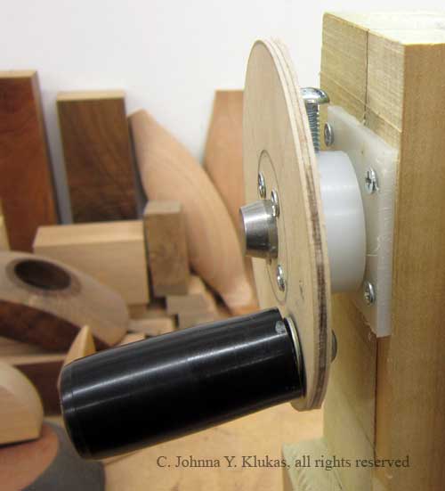
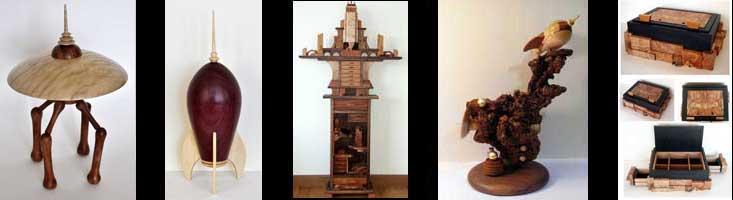
Photo 6
The handle assembly consists of the spacer and set screw, handle wheel and the crank. It serves a couple of purposes. It secures the spindle in the auxiliary headstock jig, and it allows me to turn the spindle easily and fairly smoothly.
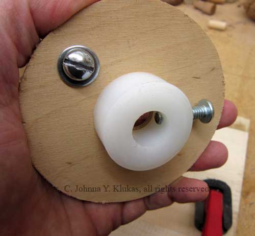
Photo 7
The spacer on the rear of the handle assembly is made of UHMW plastic. I drilled and tapped a hole to accomodate a 1/4"-20 machine bolt to act as a set screw to secure the spindle in the headstock. There's no magic to the 1/4"-20 bolt size, I just happened to have one on hand. One of these days I'll either get a shorter bolt or cut off the excess on this bolt.
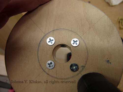
Photo 8
Again, glue and UHMW plastic don't cooperate with each other, so I screwed the spacer to the plywood wheel. Note that there's no magic to the handle wheel shape, either, I just decided to make it a circle on a whim. I have some other thoughts on handle designs that I'll discuss at the end of the article.
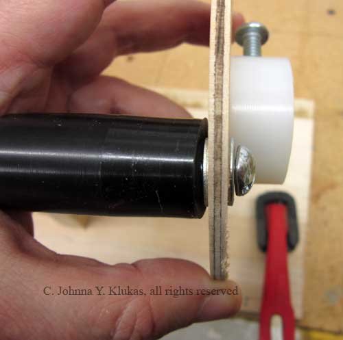
Photo 9
The crank is another piece of UHMW plastic, turned and drilled for a 1/4"-20 bolt on the lathe, then tapped by hand. I used washers on either side of the handle wheel to help the crank spin more freely. I had to tinker with the tightness of the bolt securing the crank to the wheel. Too tight and the crank doesn't turn at all, too loose and it hangs up in the hole and doesn't turn smoothly. A thicker wheel might help here.
Photo 10
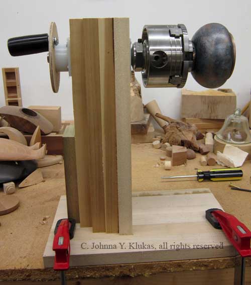
The jig in use. This is a small box I'm working on. I used the jig to hold the still-chucked box and apply dye and metallic waxes.
IDEAS FOR FUTURE MODIFICATIONS
When accomodating particularly large lathe swings, a tall headstock block may not be practical. One way to get around this would be to keep the headstock length so it's at a comfortable - and stable - height on the benchtop, while shortening the base plate so it doesn't extand past the threaded portion of the spindle. Then the jig can be clamped at the very edge of the workbench, with the workpiece also hanging over the edge of the bench but not coming into contact with the bench. If you have a lathe with a moveable headstock, think of this approach like moving your headstock to the end of the lathe bed so you can turn pieces that are larger than the nominal swing of your lathe.
The handle assembly needs to fulfill two functions: securing the spindle in the headstock and allowing you to turn the spindle smoothly. My handle wheel is 1/8" thick plywood, and the crank rocks around a bit when I use it to turn the spindle. I think going to a thicker wheel, maybe 1/2" or even 3/4" thick material, would support the crank's bolt better and lead to a less sloppy movement.
Another possibility is to turn the handle assembly as a single cylinder with a 5/8" hole drilled in one end to accomodate the end of the spindle, and tapped for a set screw. Then the whole cylinder/handle assembly is the crank. This would be similar in design to the cylindrical handwheel on my Jet 1642 lathe. I'd experiment with the cylinder diameter so it's comfortable in my hand, and with the cylinder length so it's long enough to get a good grip on but not so long that it's awkward to use.
Page last updated 3 May 2012